The 1E7G regenerative radio circuit pdf is an explanatory book for both radio enthusiasts and students who are studying vintage radio technology. The regenerative receiver generally formed the basis of radio communication development as it was capable of receiving far-station signals with very few components. This blog explores the details of the 1E7G regenerative radio circuit and its design, functionality, applications, and benefits.
What is a Regenerative Radio Circuit?
A regenerative radio circuit is one type of simple receiver using feedback to amplify weak radio signals so that it can accept distant stations. In particular, the design of the 1E7G regenerative radio circuit is known for being a ‘classic’ example of simplicity and efficiency and is very widely used in amateur radio work and education.
History of Regenerative Receivers
Edwin Armstrong developed the concept of regenerative reception at the dawn of the 20th century. He did transform the radiation technology because, with it, receivers could capture too weak, indistinguishable signals that could not be detected before. The regenerative circuit made possible sensitivity and selectivity to increase, so users could tune in to numerous frequencies without requiring precise components.
The 1E7G Regenerative Radio Circuit: Overview
One of those very specific designs utilizing the reliable and versatile 1E7G vacuum tube is the 1E7G regenerative radio circuit. The circuit finds common applications in low power applications, such as hobby, experiments, and educational demonstrations.
Important Circuit Components of 1E7G Circuit
The 1E7G regenerative radio circuit PDF consists of the following important components that play a crucial role in its operation:
- 1E7G Vacuum Tube The backbone of the circuit is 1E7G, which works as both detector and amplifier, so the tube will make it very ideal for use in the regenerative designs.
- Tuning Coil This component will assist in selecting desired frequency since the inductance in the circuit changes. The tuning coil is normally connected to a variable capacitor, which supports fine-tuning of the reception.
- A variable resistor, often installed for adjusting the level of feedback, is required to ensure an ideal compromise between gain and stability in the 1E7G regenerative radio circuit.
- Power Supply. It typically needs a DC power source that ranges around 6-12 volts according to its design specifications.
- Antenna. It needs to capture the radio waves by the appropriate type and length of antenna; otherwise, it would severely compromise the quality of reception.
How the 1E7G Regenerative Circuit Works
Basic understanding of how the 1E7G regenerative radio circuit works involves knowing the basics of RF signals and amplification.
Basic Working Principles
- Signal Receipt: The Antenna captures the RF, which is then fed into the tuning coil.
- Tuning: The frequency band being received can be selected by the operator by adjusting the variable capacitor with the tuning coil.
- Amplification and Feedback: The 1E7G tube amplifies the received signal. A portion of this amplified signal feeds back to the input stage through the variable resistor controlling the feedback level.
- Regeneration: Due to this feedback, the circuit begins oscillating, which enhances the gain and enables the detection of weaker signals, and the operator adjusts the feedback for the best performance free from instability.
- Audio Output: The amplified signal is converted into audio frequencies that can be heard from a connected speaker or headphones.
Circuit Diagram
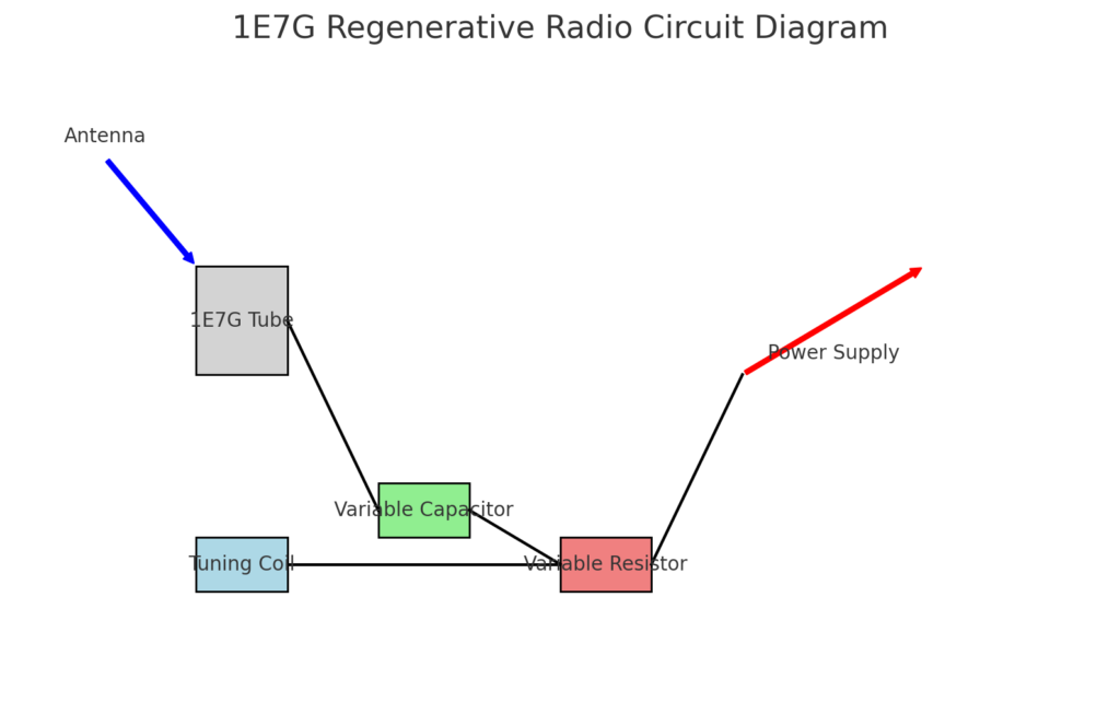
A simple circuit diagram helps understand the 1E7G regenerative radio circuit PDF much better:

In this circuit diagram, one can visualize the layout of the components and the flow of the signals within the circuit. The above circuit diagram acts as a guide in building or troubleshooting a regenerative receiver.
Applications of the 1E7G Regenerative Radio Circuit
The 1E7G regenerative radio circuit has various uses, especially in amateur radio and educational projects. Major usage of the same circuit includes the following:
- Amateur Radio
Many amateur radio enthusiasts build regenerative receivers to explore different frequencies and modes of operation. For this purpose, the 1E7G regenerative radio circuit has become very popular due to its ease of construction and efficiency, giving it good consideration as a beginners’ project. - Educational Demonstrations
The regenerative radio circuit is a great teaching medium for classifying basic electronics, radio frequency communication, and signal processing concepts. Students can learn about feedback, amplification, and tuning from the 1E7G regenerative radio circuit PDF. - Low Power Communication
The 1E7G regenerative radio circuit is useful for low-power communication systems, for example, personal radio stations or short-range transmission. Due to the fact that it has an ability to enlarge weak signals, this circuit is excellent for these purposes. - Restoring the Old Stuff
Many radio hobbyists look into the domain of restoring old radio equipment. The 1E7G regenerative radio circuit can be used to recreate old radios, preserving the historical value while providing a practical demonstration of early radio technology.
Advantages of the 1E7G Regenerative Radio Circuit
The 1E7G regenerative radio circuit has so many advantages, which is why many hobbyists and teachers adore it.
- Design Simplicity
Unlike other types of receivers, the 1E7G regenerative radio circuit PDF requires fewer components in the basic design. This reason allows it to be approached even with a minimal understanding of electronics and is very accessible to beginners. - Cost Effective
With the minimum number of components and the 1E7G tube, the regenerative radio circuit can be very reasonably constructed, so it certainly serves as an amateur option for people who are on a budget. - High Sensitivity
The design used in the regenerative circuit allows for high sensitivity, whereby users can pick up weak signals that they would not be able to get if the design were not that complicated. This is highly useful for amateur radio operators searching for distant stations. - Educational value
Building up and checking a 1E7G regenerative radio circuit PDF is an excellent educational tool in electronics and radio technology, as it requires and stimulates problem-solving and critical thinking during the circuit troubleshooting and optimization. - Flexibility
The design can be easily modified or extended with new components for the testing of different configurations, components, and tuning methods to encourage creativity and innovative adaptation of radio projects.
Challenges and Limitations
Although there are many advantages of the 1E7G regenerative radio circuit, some difficulties and limitations in this circuit must also be acknowledged:
Stability Problems
Regenerative circuits may sometimes be unstable because of a high feedback value. The instability can cause oscillations that will make a circuit unusable till it is properly tuned.
Limited Frequency Range
Unlike the superheterodyne receivers, in a 1E7G regenerative circuit, the frequency may be restricted up to a certain limit so the user may not be able to operate some bands.
Susceptibility to Interference
The regenerative receivers are susceptible to interference of close electronic devices, which degrades the quality of received signals.
Skill Level Requirement
Even though this is a relatively simple circuit, some minimal knowledge of electronics and radio theory is assumed and must be worked out by you in order to build and debug the circuit successfully. Beginners can be easily baffled without good instructions.
Building Your Own 1E7G Regenerative Radio Circuit
Do you want to make your own 1E7G regenerative radio circuit? No problem. Here’s a step-by-step guide to follow and get you off to a good start.
Materials Needed
- 1E7G Vacuum Tube
- Variable Capacitor: e.g., 10-100 pF
- Tuning Coil: 10 turns of insulated copper wire
- Variable Resistor: (example, 100k ohms)
- Power Supply: (6-12 volts DC)
- Speaker or Headphones
- Antenna: (a simple wire antenna will suffice)
- Circuit Board or Breadboard: (for assembling components)
Step-by-Step Instructions
- Prepare the Circuit Board: Lay out your components on the circuit board or breadboard. Leave room for all components and be sure they are accessible.
- Connect the 1E7G Tube: Put the 1E7G vacuum tube in its socket. Refer to the datasheet of the tube about how to insert it with the right pin configuration.
- Tuning Circuit Assembly: Connect the tuning coil with the variable capacitor. Together these enable the selection of frequencies. Attach one end of the coil to the antenna and attach the other end of the coil to the tube.
- Connect the output: from the tube to the variable resistor. This resistor will provide feedback stability, regulating the level of feedback appropriately.
- Use a power supply to connect to the circuit. Ensure correct polarity so you do not damage any of the components.
- Used the Circuit: After assembly, connect the power source and adjust the variable capacitor and resistor to tune a station. Listen for a sound through the speaker or headphones.
- Optimization: Experiment with different configurations and components to optimize performance. Record your observations for reference in the future.
Conclusion
1E7G Regenerative Radio Circuit PDF Long regarded as a marvel of engineering, the 1E7G regenerative radio circuit PDF is marvelous science that shows the essence of early radio communication. This circuit is very simple, very effective, and carries full educational value; for these reasons, it has become one of the favorite circuits for hobbyists, teachers, and even older radio enthusiasts. As people learn to understand its design and operation, they can also explore the world of radio with all its excitement.
